
COMPUTER CONTROLLED MACHINING
GOALS FOR THE WEEK
- Complete your lab's safety training
- Test runout, alignment, speeds, feeds, and toolpaths for your machine
- Document your work to the group work page and reflect on your individual page what you learned
- Make (design+mill+assemble) something big
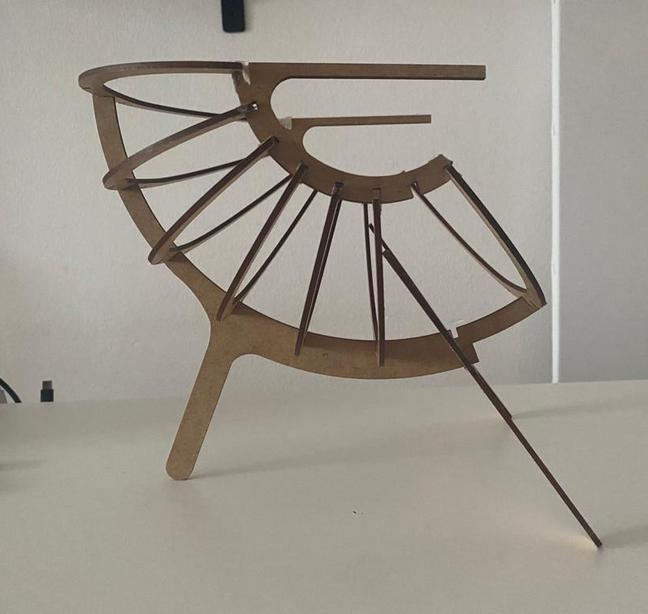
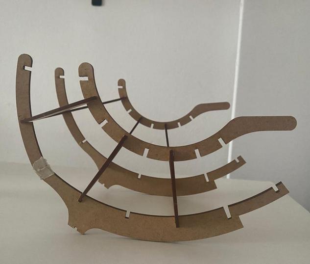
- 1. One central spine, 9 semicircular pieces for the body and 2 front legs.
- 2. two central spines, 9 semicircular pieces for the body and 2 front legs.
- Make sure you have the right machine chosen, in my case it was the shopbot.
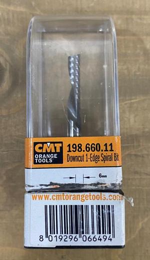
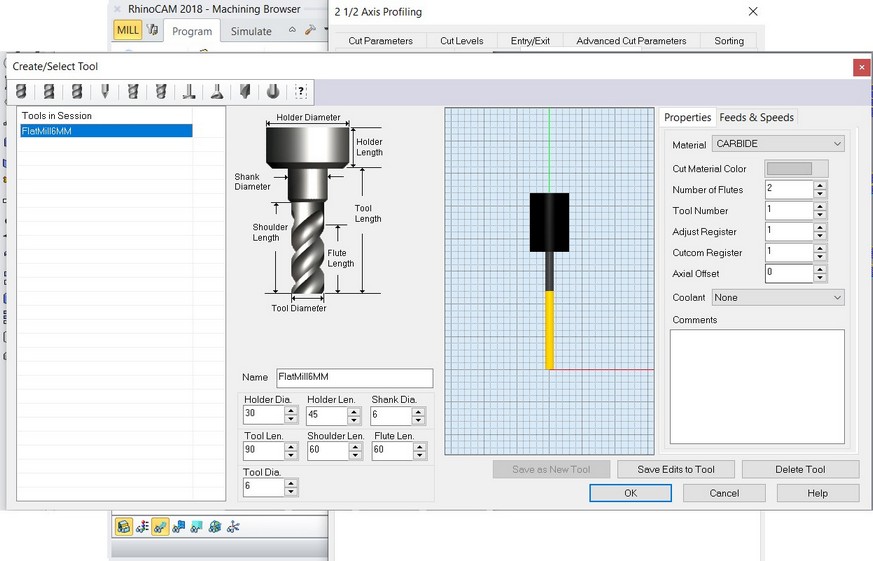
- I used a downcut 6mm dia flat endmill with 1 flute.
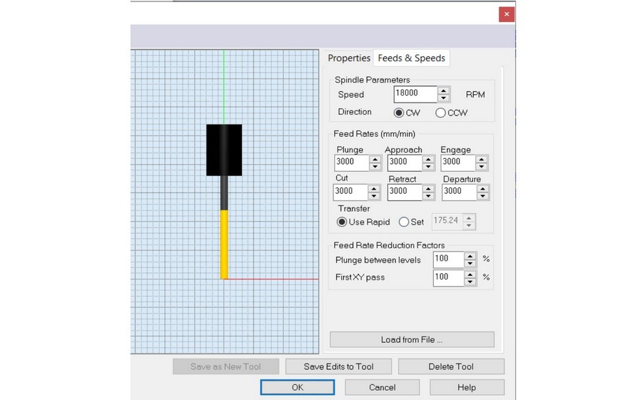
- Creating the tool: Change the tool diameter, length as per specifications on the endmill and calculate the feeds and speeds.
- Calculating Feeds and Speeds
- We start by making points which would be engraved to screw the board in place. Create an operation for the same and make sure you update:
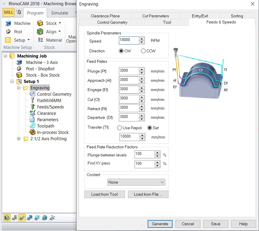
- Feeds and speeds.
- The tool.
- The start/Origin.
- The cut depth: a few mm.
- Feeds and speeds.
- The tool.
- The start/Origin.
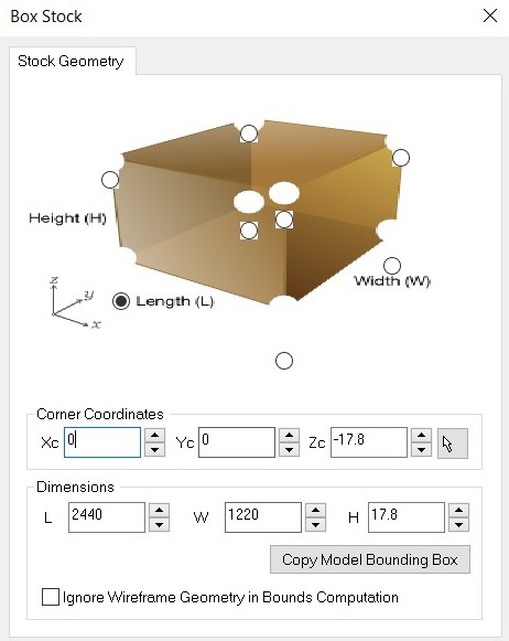
- The thickness of the material, cut depths and number of passes.
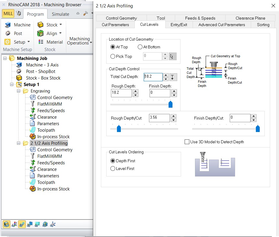
- Start the simulation to crosscheck everything and save the milling file seperate from the engraving one.
GROUP
INDIVIDUAL
Link to the group assignment: TEST
DESIGN
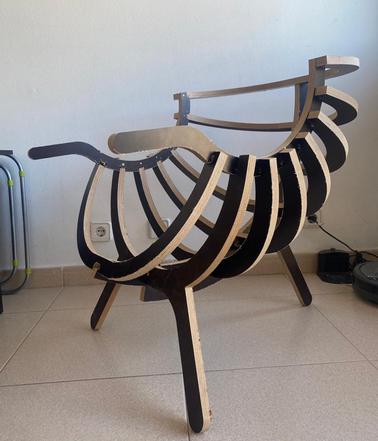
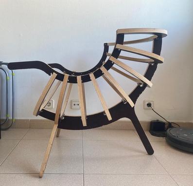
I took inspiration from a chair design by sculptural shell chair by Portuguese Designer Branca Lisboa and modelled my version of it on rhino.
.jpg)
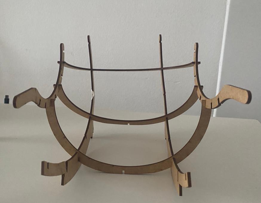
I started the design with the spine and arms of the chair which were two semicircles with another semicircular piece connecting them. The other 9 pieces make up the body of the chair. The front legs are connected to the spine and they stand at an angle.
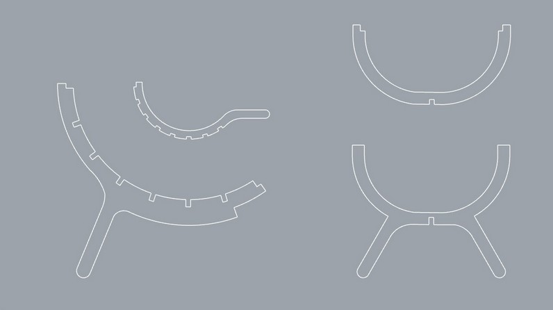
Adding the dog bones: I added the dog bones mannually on Rhino.
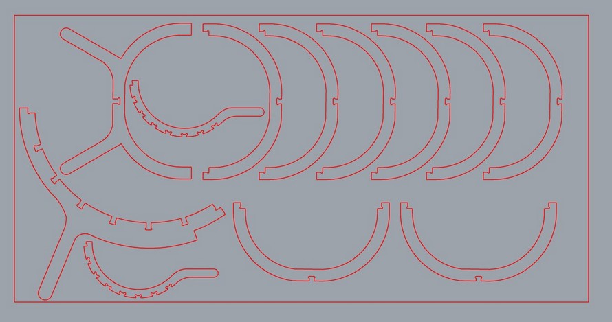
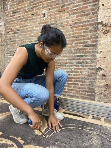
I decided to first do a test of a scaled down version of the model. I used 3mm MDF and make two versions of the chair.
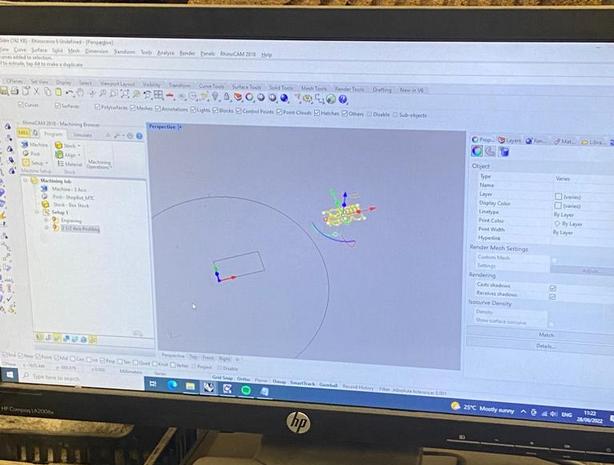
RHINOCAM
Chip load = fm / flutes (rpm) = value is always in inches per minute.
fm = feedrate
flutes = number of flutes
rpm = rotation
chip load = how fast should your endmill move horizontally
This equation works if you cut using:
Cut depth = tool diameter / 2
(Use an online calculator)
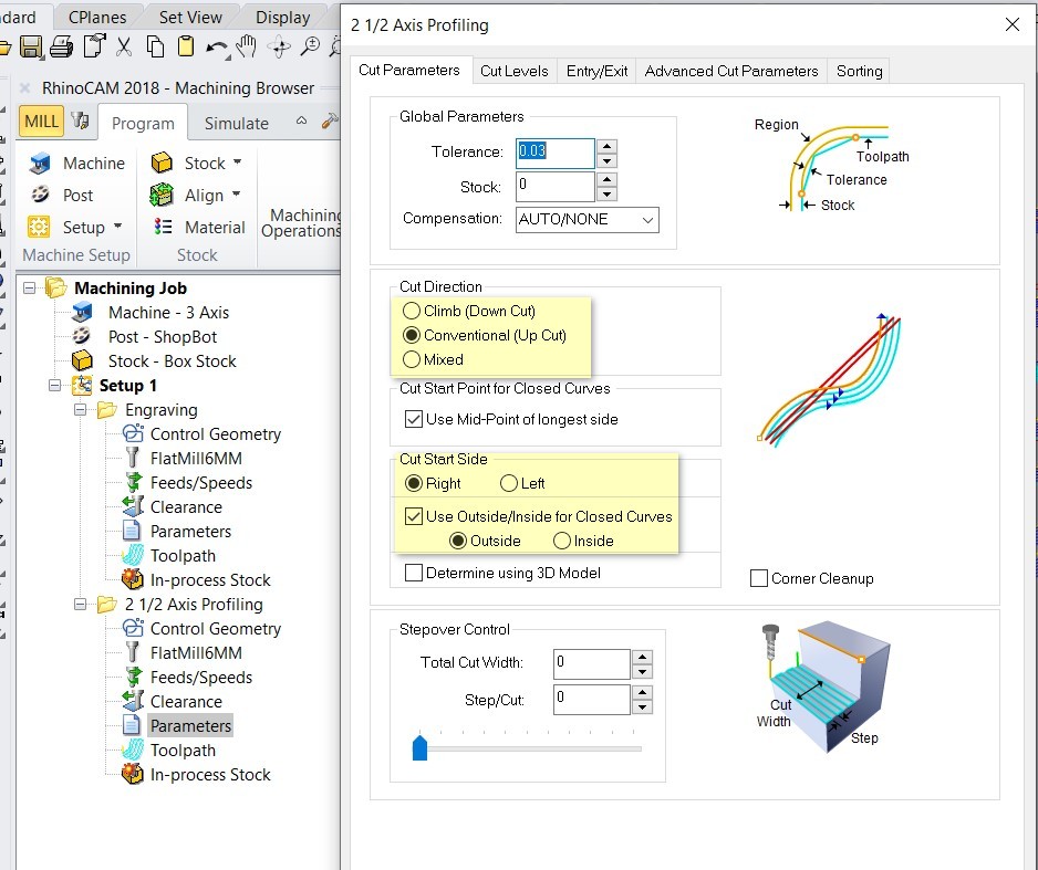
Create an operation for the milling: PROFILING
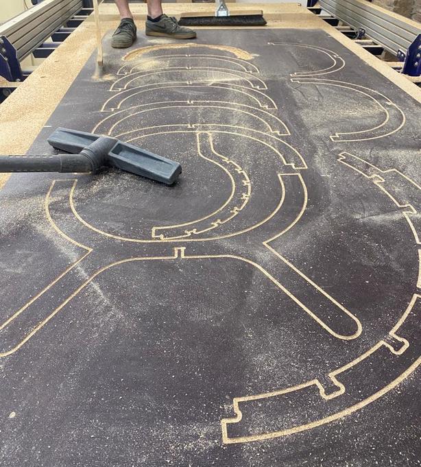
MILLING
For milling I had to use the Shopbot CNC router
The layout of the machine:
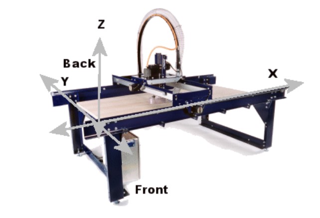
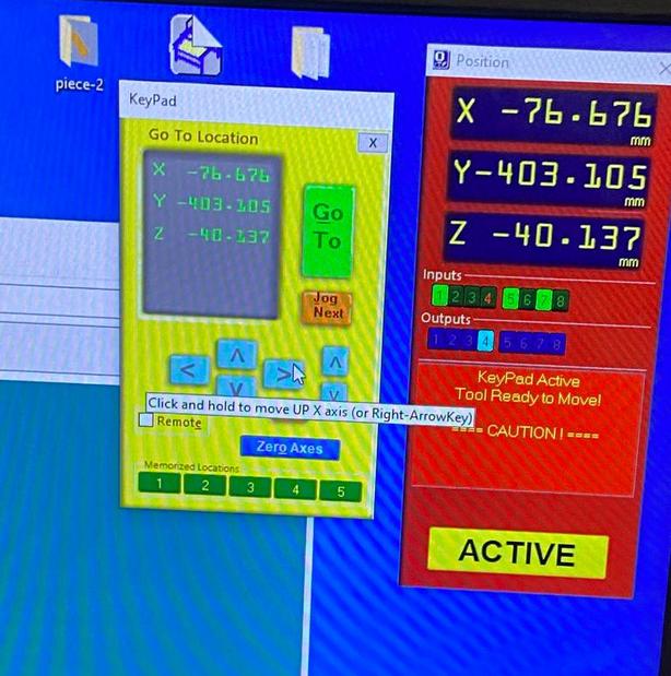
The user interface:
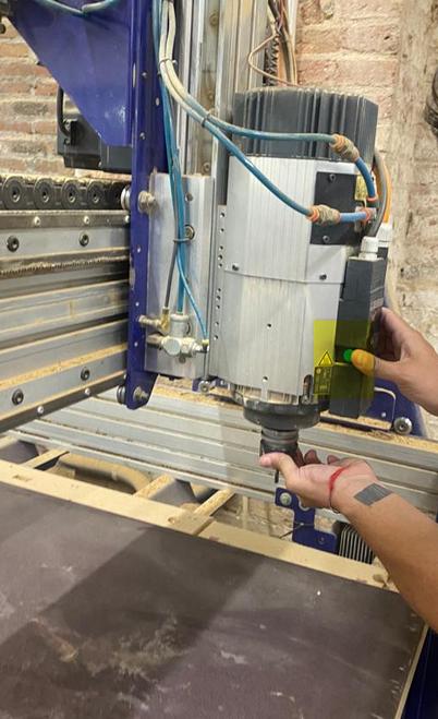
Attaching the endmill to the collet:
The shopbot follows a very simple way of attaching the endmill to the machine using a single button that can also be controlled by the computer.
Setting the origin: I set the X and Y axis in the bottom left corner of the machine and for the Z axis the machine uses a metal-metal contact system or the axis has to be set mannually.
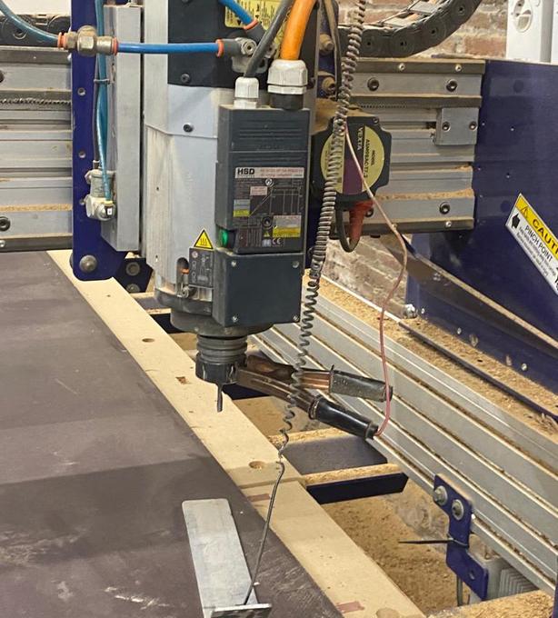
> The first part of the milling is engraving the drill holes. I had to secure the material in with screws.
> When I started the mill, the endmill moved to the other corner of the machine, Eduardo pointed out that my drawing was not set at the origin. After changing that, the milling went well.
THE RESULT
I got most of the tolerances right except with the spine. So, I am planning to use some spacers to fix it and also screw some joints in for safety before using the chair. I would definitely change some minor things in the design for the next iteration to make it more stable. Overall, I am happy with how it turned out.
Design files download
Rhino file